
Nozzle Design Calculations
Nozzle Design Calculations, Indeed recently has been hunted by consumers around us, perhaps one of you personally. People now are accustomed to using the internet in gadgets to view video and image information for inspiration, and according to the name of this article I will discuss about
If the posting of this site is beneficial to our suport by spreading article posts of this site to social media marketing accounts which you have such as for example Facebook, Instagram and others or can also bookmark this blog page.
05 How Do I Design A Custom Flange On A Nozzle Autopipe Wiki Autopipe Bentley Communities Gas Nozzle Mig
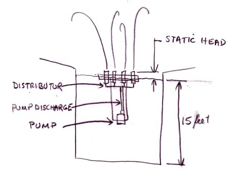
Fountain Pump Tutorial Gas Nozzle Mig

Thermal Design Considerations For Centrifugal Compressor Piping Systems Page 2 Of 3 Compressortech Gas Nozzle Mig

Aerospike Nozzle And Minimum Length Nozzle Design Gas Nozzle Mig

Pdf Design Calculation Of Nozzle Junction Based On Asme Pressure Vessel Design Code Gas Nozzle Mig
Nozzle Operating Instructions Gas Nozzle Mig
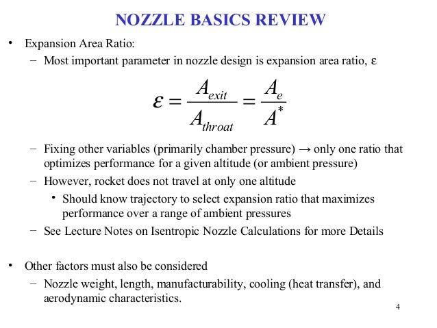
A 2 outlet area m 2 a c throat area m 2 n index of expansion.
Gas nozzle mig. The relationships for flow rate pressure loss and head loss through orifices and nozzles are presented in the subsequent section. So some extra thickness and hence area is available in the nozzle itself. V 1 inlet specific volume m 3 v c outlet specific volume m 3 c 2 outlet velocity msec c c throat velocity msec r pressure ratio p 1 p 2.
Displaystyle beta frac d o d 1 b d1. B d o d 1. This thickness can be discounted in the calculations of the actual area that is lost and which must be compensated through the provision of a reinforcement pad.
This available extra nozzle thickness up to a height of h1 above the header od can be accounted for in the area available in the original design. Beta b the ratio of orifice to pipe diameter which is defined as. Calculates the flow rate from a nozzle for a specific pressureand flow rate.
Design calculation of nozzle junction based on asme pressure vessel design code. 425 b make it possible to increase the yield of median particle size powder 4060 mm by maximizing the gas velocity and density at the meeting with the metal stream 32however the use of these units can cause the freezing of the molten metal at the end of the tundish nozzle which immediately stops the atomizing. R c critical pressure ratio.
These relationships all utilise the parameter. Such a nozzle is called self compensating nozzle. 1 e joint efficiency for or the efficiency of appropriate joint in cylindrical or spherical shells or the efficiency of ligaments between openings whichever is less.
The nozzle feature design does not have a repad feature and is onlyapplicable for internal pressure only. This nozzle design fig. In a similar way the nozzle thickness is calculated.
Basics Of Space Flight Rocket Propulsion Gas Nozzle Mig
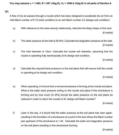
Solved You May Assume Y 1 403 R 287 J Kg K Cp 1 Chegg Com Gas Nozzle Mig
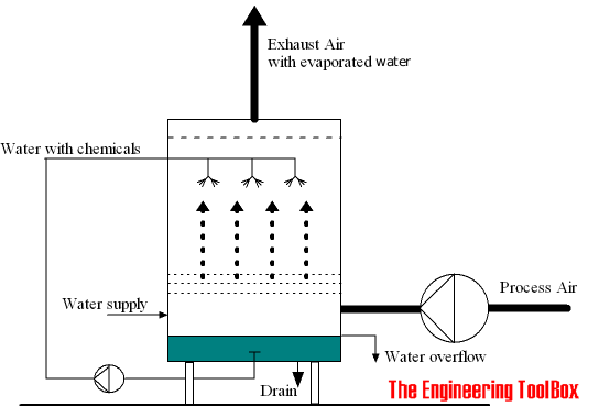
Scrubber Basics Gas Nozzle Mig
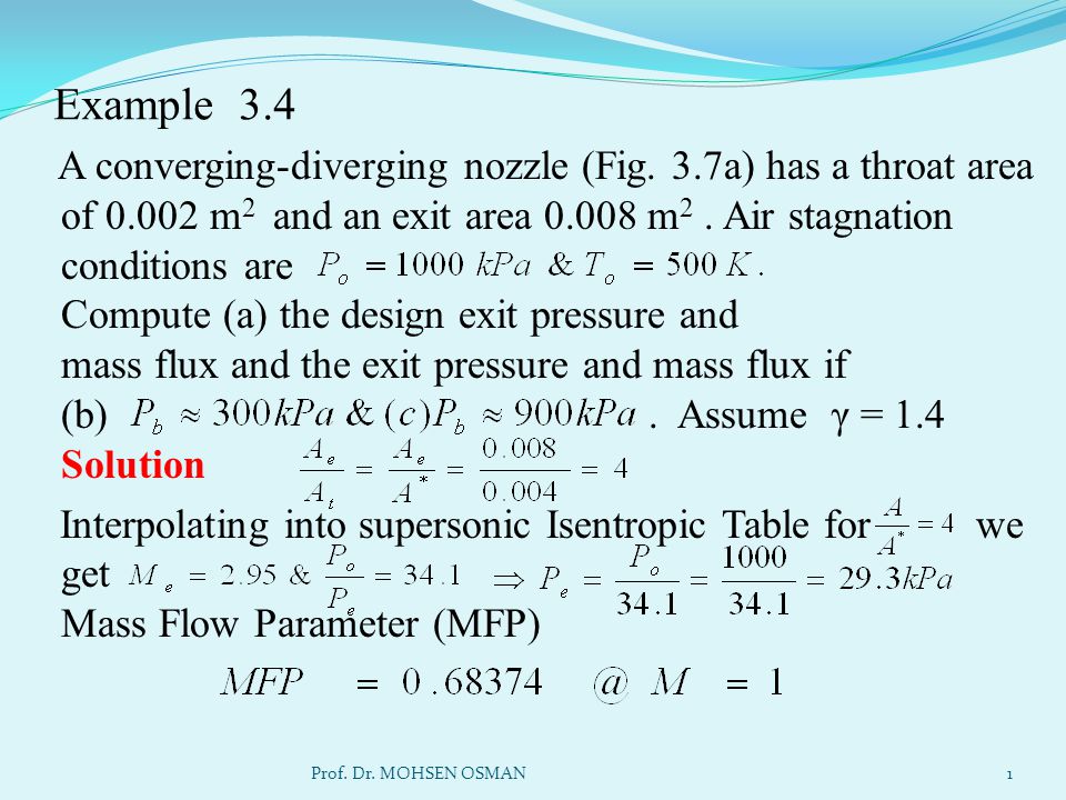
Example 3 4 A Converging Diverging Nozzle Fig 3 7a Has A Throat Area Of M2 And An Exit Area M2 Air Stagnation Conditions Are Compute Ppt Video Online Download Gas Nozzle Mig